How to build a vehicle demonstrator (fast)
Talk to engineers who’ve been here before
If you’re responsible for an EV program and want to reduce uncertainty before it becomes risk, let’s talk.
Share:

A trade fair is three metres of carpet and eight seconds of attention. You can spend those eight seconds explaining that your company makes electric vehicles behave predictably, or you can hand somebody a transmitter and let them try to make a car misbehave. We decided to build the car.
The problem with control software is that it is invisible when it works. A vehicle that holds itself on a slope looks like a vehicle parked on a slope. Our actual work lives in models, on test benches and inside customer vehicles, none of which fit in a flight case or belong to us to show. So we wanted a vehicle small enough to carry, cheap enough to risk, and real enough that nobody mistakes it for a toy. And we wanted it quickly, because the next fair does not move.
What we set out to build
- A demonstrator vehicle programmable with automotive software written in MATLAB and Simulink.
- A microcontroller evaluation board running the control algorithms and sending a torque command over CAN to the motor controller.
- Scale between 1:8 and 1:10, so it draws attention and does not read as a toy.
- Able to hold itself on a 15 percent slope, unaided.
- Total vehicle weight around 6 kg, not more.
- Regenerative braking possible.
- Preferably with integrated brake lights the evaluation board can drive.
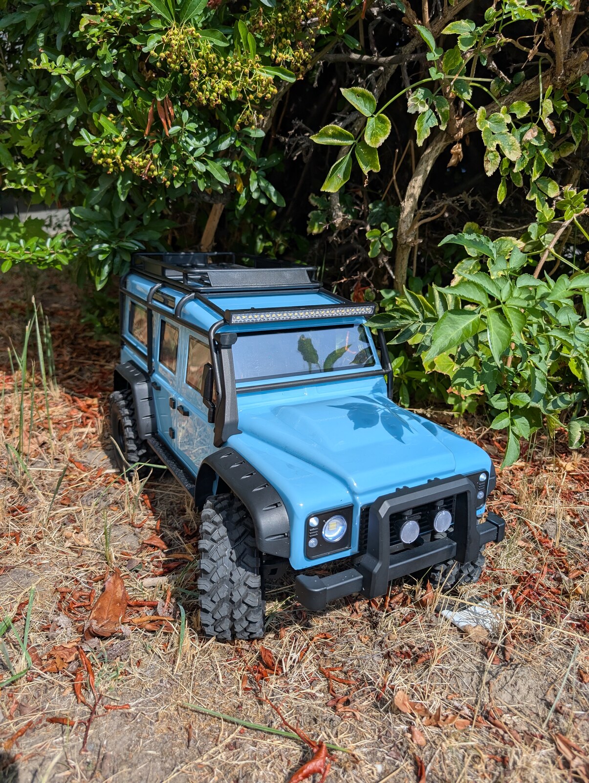
Those requirements picked the vehicle for us. We needed price and performance in balance, enough real drivetrain to have something to control, lighting, room for extra electronics, and a body that looks like a vehicle rather than a fantasy shape. A 1:8 scale Defender-style crawler met all of it.
Why does renco also build a demonstrator?
Electrification rarely fails because somebody picked the wrong component. It fails when propulsion, controls, safety and suppliers are not aligned as one system. That is a difficult argument to win in conversation and an easy one to win on a table: put the car on a ramp, hold it there with hill hold active, then untick the box in the calibration tool and let it roll back.
Every strategy on the vehicle is bound to a calibration switch, reachable while the car is running. The same obstacle, the same driver input, the software on and then off. That is the demonstration, and it is the reason the car exists rather than a slide about it.
It earns its keep internally too. New strategies, diagnostics and validation methods can be tried on a scaled vehicle before they are proposed for a customer programme, and an engineer joining renco can work through the whole chain, requirement to model to code to calibration, on hardware they can pick up. A mistake costs a plastic gear.
How did we get something running quickly?
The first version was deliberately crude. We left the vehicle's original brushless controller in place and did nothing more than read its servo signal at the evaluation board, modify it, and output it again. That alone proved the toolchain: a Simulink model, generated code, real signals in and out, on the actual vehicle, within days.
It also showed us its own limits immediately. Passing a servo pulse through gives no regenerative braking and no control over torque, because the original controller only accepts a throttle position and keeps its own counsel about what it does with it. To control torque we had to replace the controller, and that decision drove everything that followed.
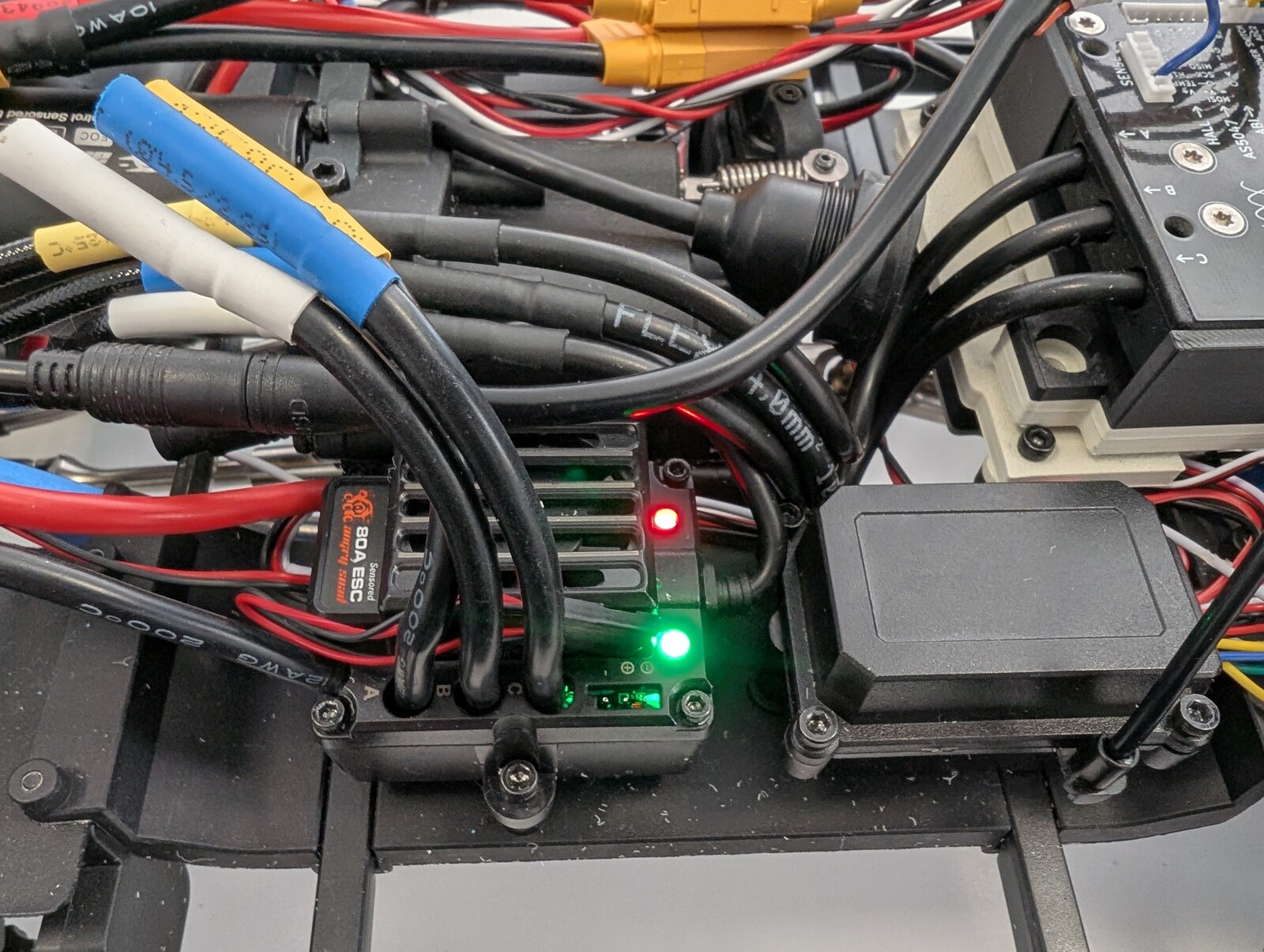
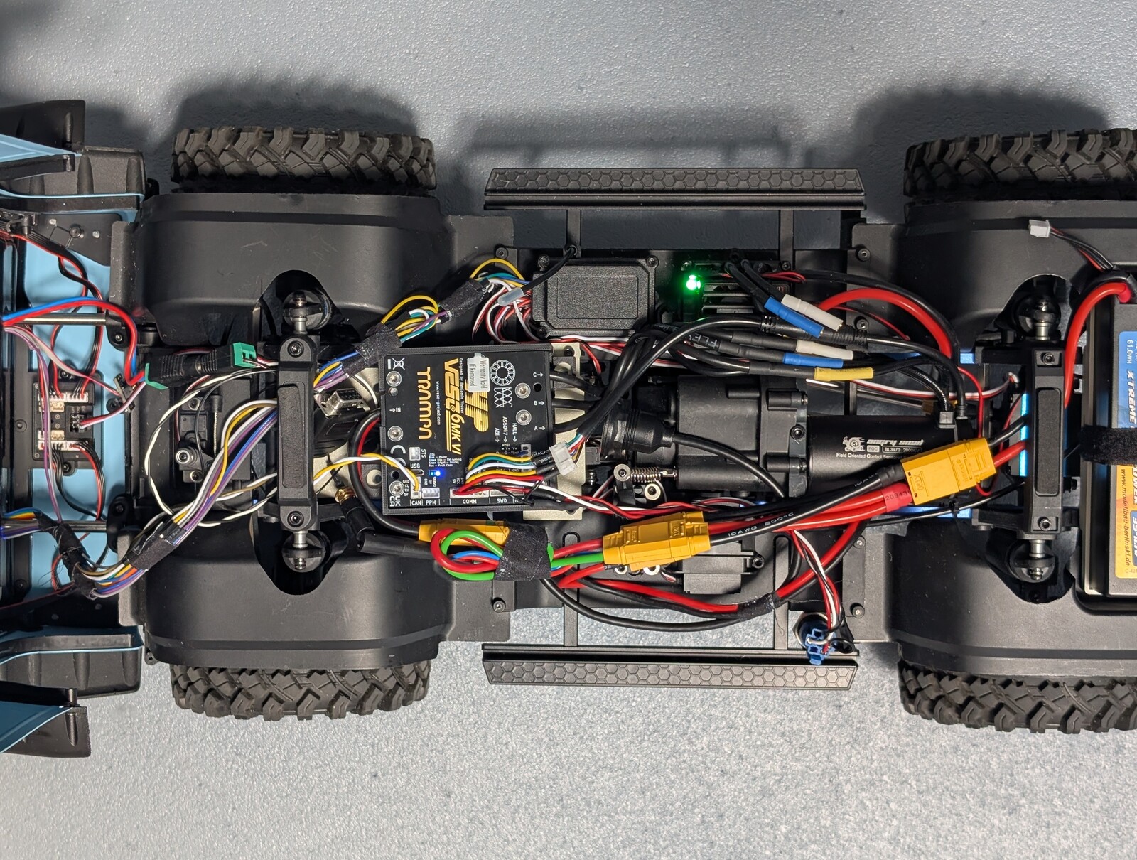
The original controller is still in the car, though not for driving. Its motor phases and its throttle input are both parked, and it earns its place by supplying the receiver, the wireless bridge and the vehicle controller from its own internal supply, so the vehicle needs no separate converter. It also means the factory drivetrain is a reconnection away rather than a rebuild away.

What is in the vehicle now?
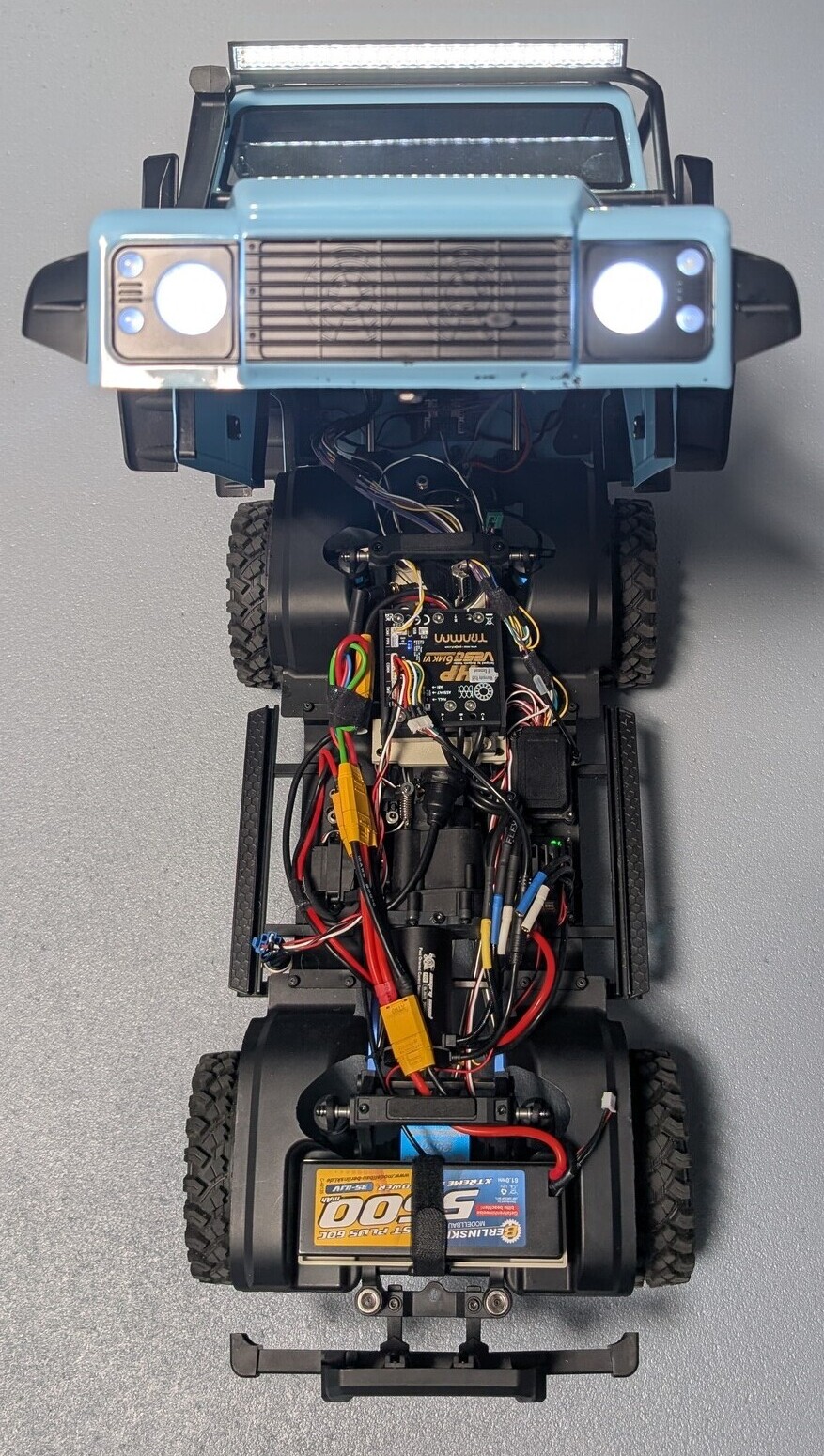
The original controller is a capable, inexpensive unit with its own smartphone app, and a closed system: no bus interface, no way for a vehicle controller to command it. It was replaced by a Trampa VESC 6 MK6 HP, which offers a CAN interface, open-source firmware and an open-source configuration tool. That openness is what turns a model car into a development platform.
Alongside it sits an Infineon AURIX TC387 evaluation board running the application software, a pair of boards forming a wireless bridge onto the vehicle CAN bus, and the original controller, refitted as the power supply for all of it. The vehicle keeps its two-speed gearbox, its lockable differentials and its lighting, which is the point: there are real drivetrain functions to control, not just a motor to spin.
How does the control chain work?
The radio link ends in an ordinary hobby servo signal. One wire per channel carries a repeating pulse, and the width of that pulse is the command: 1.0 ms at one extreme, 1.5 ms at the centre, 2.0 ms at the other, repeating about every 20 ms. What matters is that the width carries the command and the repetition rate does not, which is why a timer capture input can read it without being synchronised to the transmitter at all.
The controller captures those pulses and normalises them. Inside the model the command becomes a torque request, which is what the strategies work with, and the torque request is then converted into a motor current. The current is what goes onto CAN. The inverter closes the current loop at its own rate and reports rotor position, speed, currents, voltage and temperatures back on the same bus, which is what the higher-level functions run on.
During development the controller drove the inverter through its servo input, so the car could be driven before the CAN path worked. That wire is gone. The command now reaches the inverter only as a current on CAN, which is what the strategies need: a torque request means nothing to an input that only accepts a throttle position.
Channel assignments follow the driver rather than convenience. Steering is captured so that steering angle is available to the strategies, not merely passed through. Throttle and brake is the primary input. Gear selection is captured so torque can be adapted to the gear actually engaged. The lighting channel is the exception: it goes straight to the vehicle's own light controller, which reads the throttle and steering pulses itself to work out brake and indicator behaviour. The capture channel for it is configured and routed on the board but left unconnected, so taking the lighting under our own control later is a wiring change rather than a redesign.
What had to be engineered rather than bought?
Assembling the parts was the small half. These are the pieces that were not available off the shelf.
A position sensor nobody documented
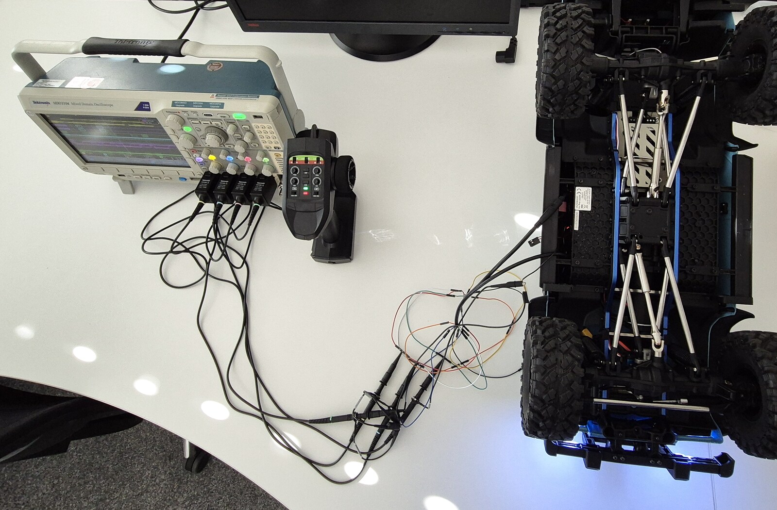
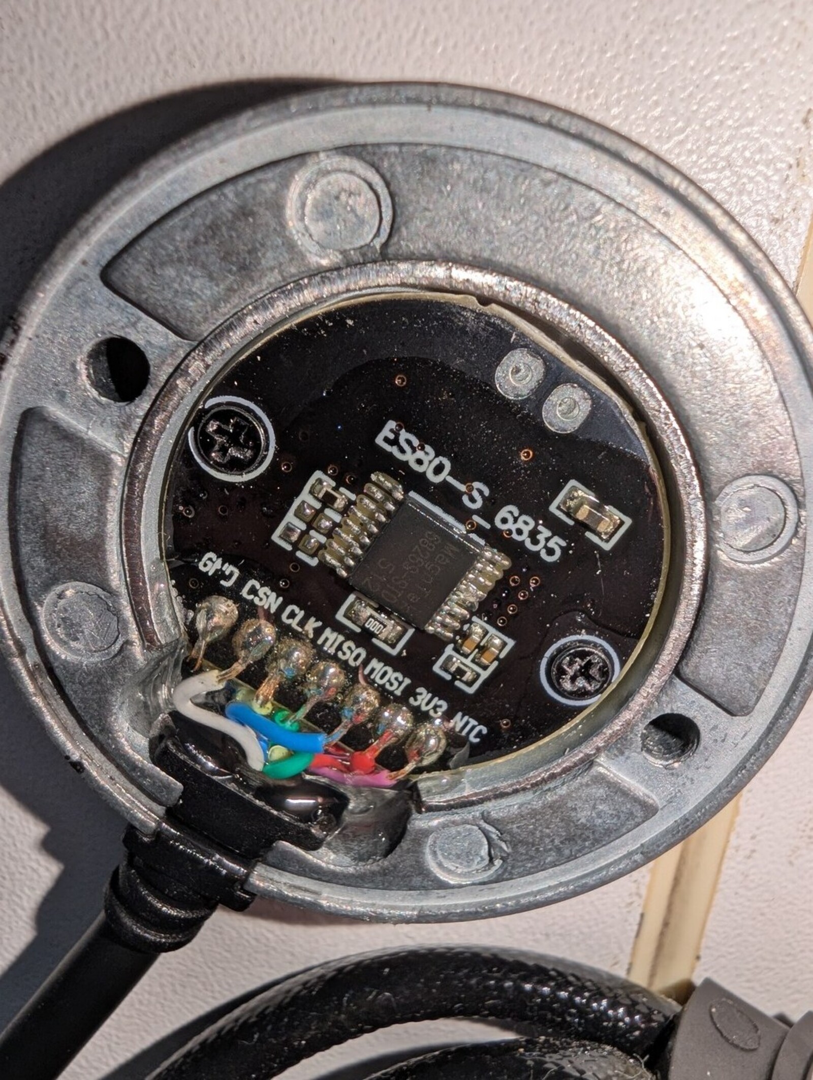
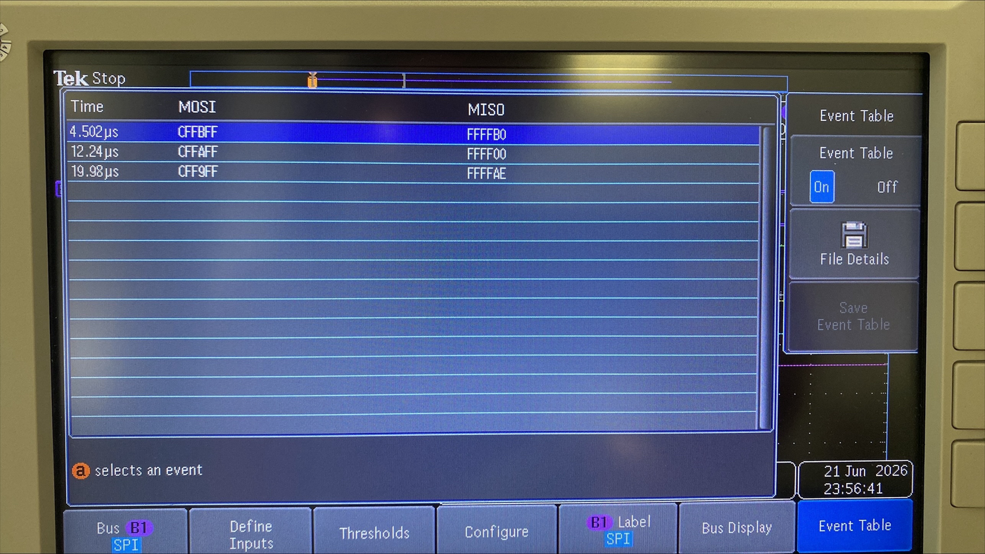
The motor arrives with a position sensor and no datasheet. At first we could not even take the motor apart, so we reverse-engineered the interface instead: probes on the sensor cable, the original controller driving the motor, and pin functions read off the captured waveforms. Four SPI lines, supply and ground, and a separate temperature signal.
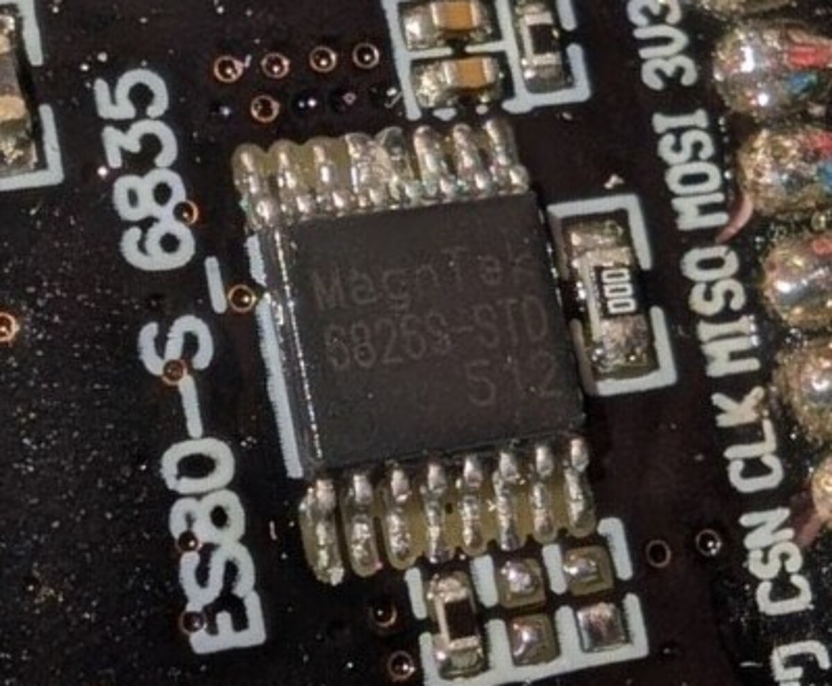
Later we managed to get the motor open, and found the sensor to be a MagnTek MT6826S, a 15 bit absolute magnetic angle encoder giving 32768 counts per revolution, about 0.011 degrees per count. The measurement had already told us how to talk to it; opening it told us what we had been talking to.
Teaching the inverter about it
The inverter firmware supports an older sensor from the same family but not this one, so we added support to the open-source firmware. The sensor has to be read over the hardware SPI peripheral, which on this board is wired to a different connector than the one normally used for position sensors, so the harness follows the silicon rather than the label. And the reported angle has to stay usable when the sensor cannot deliver a fresh reading. The sensor returns a status with each measurement and flags conditions such as weak field, overspeed and undervoltage; while that status is set, the angle published on CAN is held at the last clean reading, so a consumer on the bus sees a stale angle rather than a corrupted one. A strategy relying on absolute position has to treat a held value as exactly that: correct a moment ago, and not evidence that the shaft has stopped.
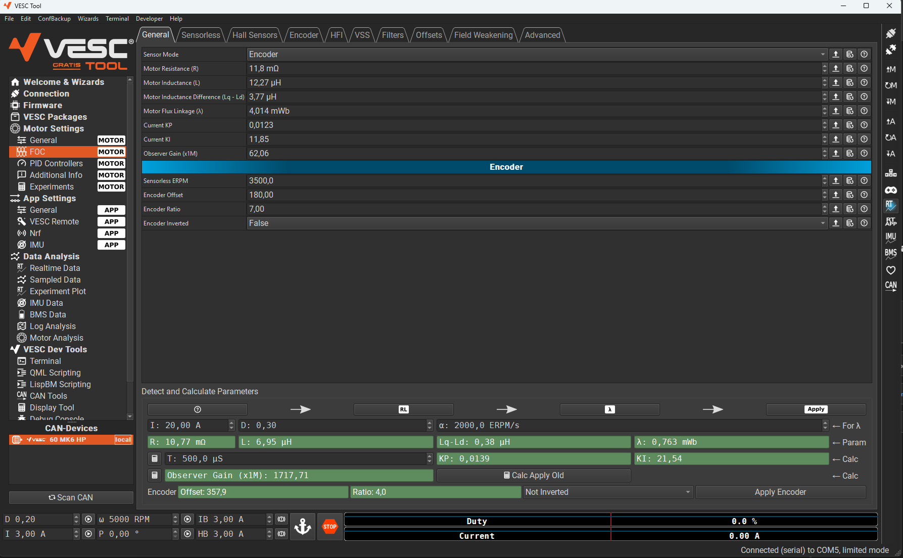
The rest is configuration rather than code. In VESC Tool the inverter is told which sensor mode to use, given the motor parameters, and then run through its detection routine, which measures the electrical offset between the sensor zero and the rotor and stores it. Without that offset the field-oriented control has no idea where the rotor actually is, and the motor either cogs or refuses to turn. It is a five minute job once the firmware underneath it is right, and impossible before that.
Making absolute position available
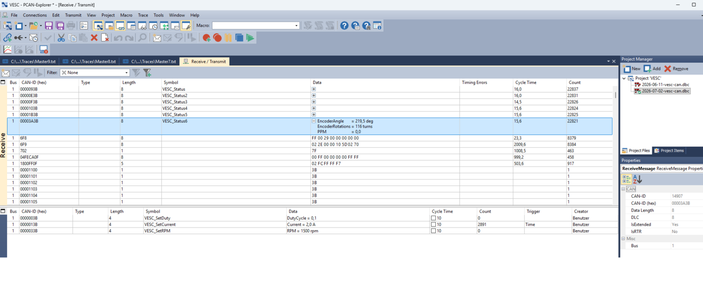
The standard inverter status messages report electrical speed and a raw commutation tick count, and neither is usable for position-based functions. We defined and implemented a custom CAN message that publishes mechanical rotor angle in hundredths of a degree together with a signed count of complete revolutions. Added together they give absolute mechanical position.
That single addition is what makes hill hold possible: the controller can hold the vehicle against a gradient by regulating position rather than inferring it from speed. It is absolute only relative to where the count started, so the strategy has to establish its own reference at the moment it engages.
CAN is not a side issue here, it is the spine of the whole thing. Every command the controller sends and every value the inverter reports crosses one 500 kbit/s bus, and both ends are generated from the same DBC file that the analysis tools load. That is what makes the traffic readable by name instead of by byte offset, and it is why a signal renamed in one place cannot quietly become a different signal somewhere else.
Measuring the gearbox
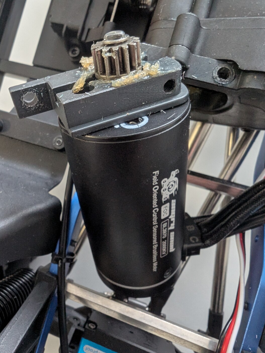
No datasheet gives the gear ratios, so we established them from the vehicle in two steps. First we trusted the instrument: turning the motor through one revolution and confirming that the values arriving on CAN matched that single rotation. Only then did we measure the drivetrain, by marking a wheel and turning it about twenty times in each gear, so that gear backlash and the error in judging the mark average out instead of dominating. The result is 43.52:1 in low and 19.45:1 in high.
Without those numbers, no torque or speed request expressed at the wheel can be turned into a motor current request. It is the least glamorous measurement in the project and the one everything else needs.
The platform helps more than it had to here. The motor comes out on two screws: slacken them, slide the motor back out of mesh and lift it clear, with the gearbox still bolted together and still in the car. For anyone who has split a transmission case to get at a motor, that is the difference between an afternoon and about a minute, and it is a large part of why this chassis was worth choosing.
Getting onto the bus without a cable
Measuring a moving vehicle over a cable is impractical, and a commercial CAN-over-WiFi interface costs about as much as the whole demonstrator. So two inexpensive ESP32 boards became a transparent bridge: one on the vehicle wired to the vehicle bus, one at the desk presenting the traffic on a short local bus that the laptop joins through an ordinary USB CAN interface. From the tools' point of view it is simply a CAN connection to a vehicle.
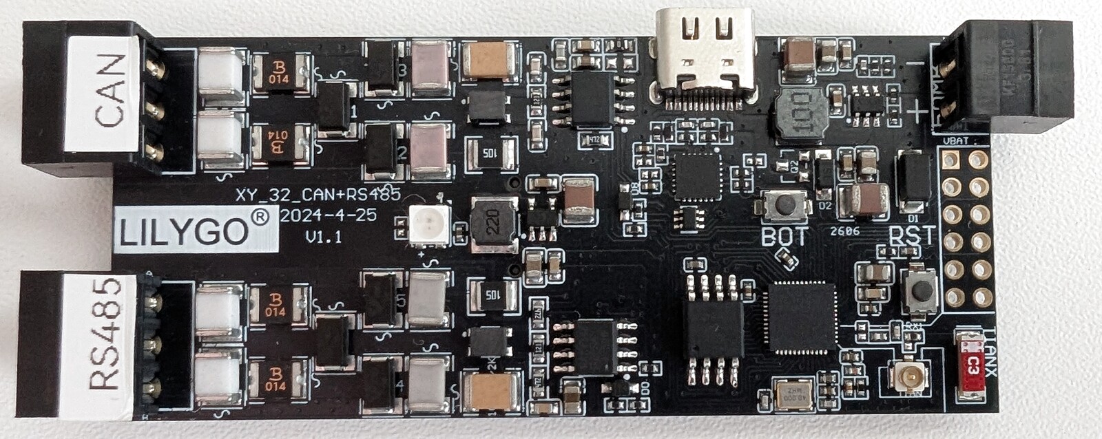
Getting to a stable, high-throughput link took considerably longer than expected, and the firmware was iterated with AI assistance. Bandwidth is still the limiting factor, because the transport has timing constraints that cap the sustainable frame rate.
Making it all fit
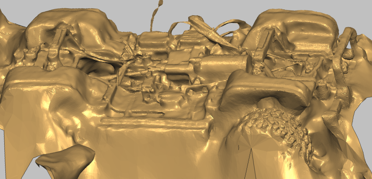
A chassis designed around one small controller now holds a vehicle controller, an inverter, a wireless bridge and the original controller as its power supply. We scanned the chassis in 3D with a phone and designed the mounting parts against the scan: a battery case for the front, because the original bay is slightly too small for the battery we wanted, and a rear bracket carrying the inverter above and the wireless bridge below.
What would we build next into the vehicle?
The comparison we kept wanting is a direct one: the same car, on the same obstacle, driven first as it left the factory and then under our control, back to back. That is a more honest demonstration than any before-and-after video, and it is now most of the way to working. Both controllers are installed. The motor phases meet at bullet connectors and the throttle lead is a servo plug, so switching between them means moving three connections rather than dismantling anything.
Wheel speed sensors and a ground-speed reference are the other addition, and they are the gate on a whole class of function: anything that compares a driven wheel against the ground, which is what slip control does, needs them. Those need to be added to the vehicle at a later point.
The bus itself is the third thing we want to build on. Both ends of the link between the vehicle controller and the inverter are ours, which makes it a place to show Secure Onboard Communication on something that visibly reacts: authenticating each torque command with a message authentication code and a freshness value computed from a symmetric key held on both sides, so a receiver can tell a genuine command from a replayed or forged one. What that costs in bus load and latency is easier to argue about on a car that stops responding than on a slide. We have written up the mechanism separately in SecOC: Secure Onboard Communication in AUTOSAR.
How is the software built?
The vehicle functions are modelled in MATLAB and Simulink against the OpenECU blockset, which abstracts the I/O and the runtime of the target. Embedded Coder generates the C code and the OpenECU build chain turns it into the binary that runs on the evaluation board. No application code is written by hand: the models are the source. The same blockset and build chain are used on production control units, so a function proven here moves to customer hardware without being rewritten.

Inside the strategy layer the structure is a chain with a feedback path. Throttle Pedal turns the driver's pulse into an intent. Torque Control forms the torque request from that intent and the measured state. Torque Arbitration decides what is actually asked for when several functions want to influence the outcome, which is exactly where hill hold, speed control, a hill-climb assistant and later a slip controller have to be reconciled rather than simply added together.

The calibration switches are not a layer bolted on top. Each output carries a pair of calibration parameters, an overwrite enable and an overwrite value, declared in the model and exported through the generated description file. With the enable off the output follows the strategy; with it on it follows the number typed into the CCP calibration tool. That is how a strategy is turned on and off in front of an audience without rebuilding or reflashing anything.
Which strategies can it run?
Everything derivable from the motor and the inverter is available today, because the inverter reports absolute rotor position, speed, current and temperature on CAN. Anything that needs to compare the driven wheel against the ground waits on sensors.

Regenerative braking sits alongside these. It was one of the original requirements and the reason the original controller had to go: a closed controller that only accepts a throttle position cannot be asked to recover energy on the way down a slope.
Come and try to break it
Which brings it back to the three metres of carpet. The car travels in a case, sets up on a table in minutes, and runs all day on one battery. At the next automotive fair it will be on our stand with a ramp and a transmitter, and anyone is welcome to pick it up and try to catch our strategies out: pull away on the slope, stop halfway, let go, change gear mid-climb, provoke it.
That is the honest version of what renco does. We design and validate the control systems that make electric vehicles behave predictably, and the only convincing way to show it is to let somebody try to make one behave unpredictably. If you are responsible for an EV programme, the same conversation is available with your vehicle instead of ours.
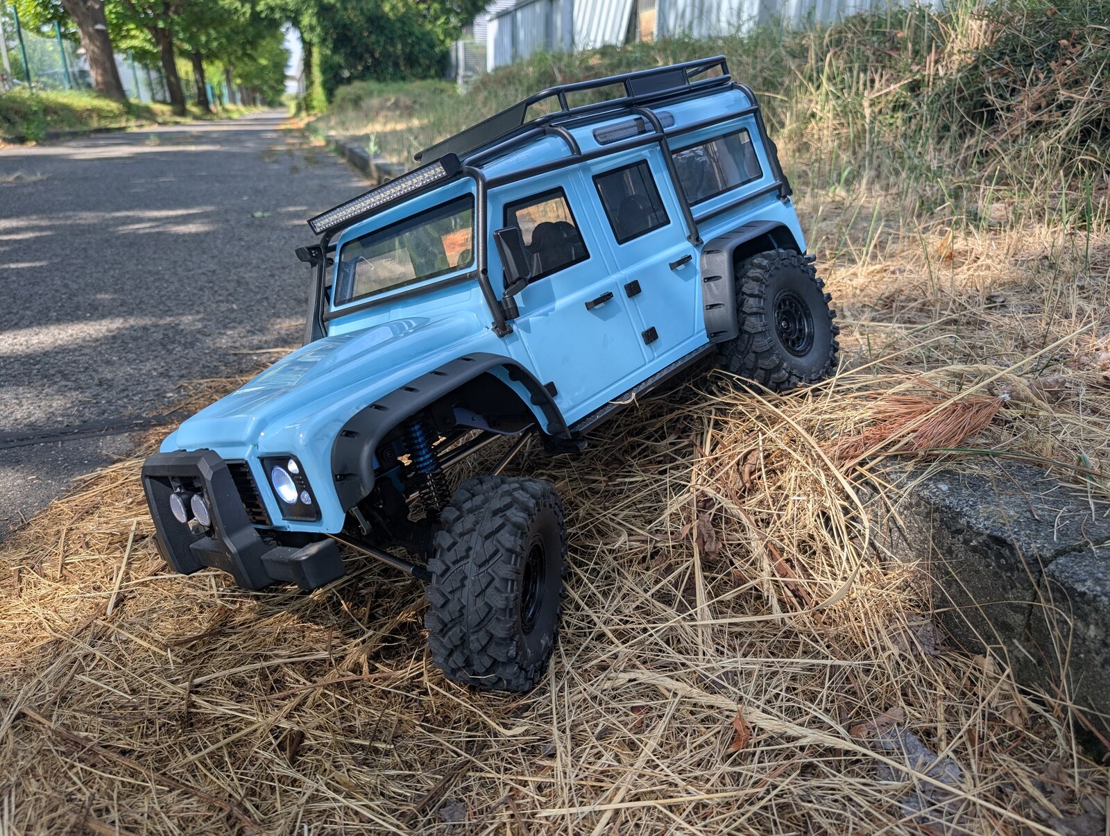
Annex: what is in the vehicle
The demonstrator mirrors the architecture of a real electric vehicle, compressed onto a 680 mm chassis. Three nodes share one 500 kbit/s CAN bus; the rest is either a driver input, a power source or a way for an engineer to see the bus.
Frequently Asked Questions
Sources

Subscribe to our newsletter
System-level insights on EV integration, control software, and validation. Written by engineers who've been building electric vehicles since 2009.