Advanced Engineering Services
Renco provides advanced engineering services for customers with higher requirements in software, safety, and compliance.

Some EV programs require more than system integration. They operate within formal automotive development processes — functional safety management under ISO 26262, cybersecurity engineering under ISO 21434, or hardware validation that goes beyond what simulation alone can confirm. The work has to fit into your architecture, your safety case, your threat model, and your validation strategy.
Renco's Advanced Engineering Services address these requirements directly — applied where software correctness, safety evidence, and hardware-level validation need to be built into the program from the start.
- Automotive Cybersecurity (ISO 21434)
- Safety-Critical Software Development (ISO 26262)
- Powertrain-in-the-Loop Testing
Cybersecurity in an automotive ECU needs to be implemented at the software and hardware level, integrated into the control architecture, and validated against the specific threats that apply to the program. The standards that govern it — ISO/SAE 21434 — require documentation and traceability that goes well beyond standard software development processes.
Renco implements automotive cybersecurity on vehicle ECUs as part of the control software development, in alignment with ISO/SAE 21434. The work covers both the technical implementation and the required work products — not as separate tracks, but as one integrated activity. Features are validated in simulation and HIL environments before reaching the vehicle, using the same toolchain discipline applied across all Renco programs.
Cybersecurity only works in context
A cybersecurity feature that is present in a platform but not correctly integrated into the program does not fulfill its intended purpose. Secure boot needs to be configured for the specific software image. Secure access levels need to map to the actual diagnostic operations the program requires. SecOC keys need to be provisioned, managed, and tied to the right CAN messages in the right architecture.
This is the gap Renco addresses. Not cybersecurity as a compliance exercise, but cybersecurity implemented and validated in the context of the specific ECU, the specific vehicle architecture, and the specific threat model. The scope of the work depends on where the program starts — some controller platforms arrive with a mature security baseline, others require implementation from the ground up.
Secure Onboard Communication (SecOC)
CAN networks in a vehicle ECU carry safety-relevant commands. Without message authentication, there is no reliable way to distinguish a legitimate message from a spoofed or replayed one.
SecOC addresses this by attaching a cryptographic message authentication code (MAC) to CAN frames, using keys stored in the hardware security module (HSM). Renco implements SecOC in the context of the controller's software architecture — including freshness value management, HSM key slot configuration, integration into the base software routing layer, and diagnostic reporting for authentication failures. The scope is defined by which messages carry safety or security relevance in the specific program.
Secure Key Storage and Key Management
Cryptographic keys need to be stored, provisioned, updated, and managed securely over the lifetime of the product. This involves selecting the right HSM configuration, defining the keystore structure, implementing secure end-of-line provisioning, and ensuring that key update operations are handled without creating vulnerabilities.
Renco handles key lifecycle management as part of the broader security architecture — including HSM key slot mapping, the update protocol, and the diagnostic interfaces that report key-related faults into the DTC framework.
Security Access and Diagnostic Session Management
Access to diagnostic functions — calibration, flashing, end-of-line programming — needs to be controlled and authenticated. This means defining which security levels map to which operations, implementing CMAC-based seed-key authentication through the HSM, and integrating the session management logic correctly with the UDS framework.
Renco implements and validates security access configurations in the context of the program's diagnostic architecture, including the mapping of access levels to cryptographic key material and the traceability of session transitions.
Intrusion Detection
Static security measures define what the system should allow. Intrusion detection provides visibility into what is actually happening at runtime — monitoring for unexpected CAN traffic, failed authentication attempts, freshness value anomalies, and cryptographic errors.
Renco integrates intrusion detection logic into the control software, connected to the J1939 DM1 and UDS DTC frameworks for event logging, fault escalation, and post-event forensic analysis. Detection scope and fault classification are defined in collaboration with the program's threat and risk analysis.
Penetration Testing
Renco coordinates and leads penetration testing as part of the validation and verification activities for cybersecurity programs. Testing is performed by independent third-party specialists, with renco defining the scope, tailoring it to the specific program, and managing execution in alignment with the threat model and security architecture.
Testing covers multiple layers — from protocol-level inspection across communication interfaces to hardware-level analysis of the ECU and its security mechanisms. This includes interface security, hardware design robustness, and verification that security controls behave as intended under adversarial conditions. Working with multiple external testing partners across different programs has built a consistent methodology for identifying gaps before the system reaches the field.
ISO/SAE 21434 Work Products
Cybersecurity engineering under ISO/SAE 21434 requires a traceable record of the decisions made, the threats considered, and the controls applied. This includes the threat analysis and risk assessment (TARA), cybersecurity requirements, design specifications, verification and validation criteria, and the cybersecurity interface agreement.
Renco produces and maintains these work products as an integrated part of the development process. The documentation reflects the actual system and the actual decisions made during the program — not a generic compliance template applied after the fact.
How scope is defined
Cybersecurity scope varies significantly by program. The right starting point is a clear picture of the controller platform, the vehicle architecture, and the threat model that applies to the specific item. If that analysis hasn't been done yet, that is where the work begins.
Implementation, validation, and documentation are performed in close coordination with the customer's engineering and security teams.
Developing software for a safety-critical vehicle system requires two things to be true at the same time: the software has to work correctly as a control system, and it has to be developed in a way that satisfies the process and documentation requirements of ISO 26262. Most software suppliers are strong in one but not both. When those capabilities are separate, interfaces break down — between the engineering team and the safety team, between what the software does and what the safety case says it does.
Renco develops safety-critical VCU software with both capabilities in-house. The functional safety competence was built through real programs — including ASIL-compliant VCU development for an autonomous vehicle platform — and is applied as an integrated part of the software development process, not as a separate compliance layer.
Where Renco operates in the safety process
In most programs, renco operates as a software supplier: developing application software to customer requirements, integrating into a customer-defined software architecture, and working within a safety concept and ASIL decomposition owned by the customer's functional safety team.
In some programs, renco contributes further upstream — supporting system requirements decomposition into software requirements, controller selection, safety concept definition, and ASIL decomposition at the software level. The level of involvement is defined by what the program actually needs.
Application software development
Renco develops VCU application software to customer safety requirements, including ASIL-classified functions. The software is developed using model-based development in Simulink, with code generation and integration into the target controller environment. Safety-relevant behavior is defined, specified, and implemented with full traceability to the safety requirements.
Integration into customer software architectures
Renco integrates developed software into customer-defined architectures — whether that means working within an existing BSW stack, aligning with defined software interfaces, or fitting into a broader system where multiple suppliers contribute components. Interface agreements and responsibility boundaries are made explicit before integration work begins.
Support across the V-model
Renco supports multiple stages of the ISO 26262 V-model — from system requirements decomposition and software requirements specification through architectural design, unit testing, integration testing, and software qualification. The scope depends on where the program needs support and what is already covered by the customer's internal team or other suppliers.
Verification and validation
Safety-critical software is verified in simulation and HIL environments before reaching the vehicle, using dSPACE toolchains. This includes functional testing against safety requirements, fault injection testing for ASIL-relevant failure modes, and generation of the V&V evidence needed to support the safety case.
ISO 26262 work products
Renco produces the work products required at the software level under ISO 26262 — software safety requirements, architectural design documentation, safety analyses (FMEA, FTA), verification plans and reports, and software safety case contributions. These are developed as part of the engineering process, in alignment with the customer's overall safety management plan.
How engagement scope is defined
The scope of functional safety support varies significantly by program — in terms of ASIL level, software complexity, the maturity of the customer's existing safety architecture, and how much of the V-model Renco is expected to cover. The starting point is always a clear picture of what the program requires and what is already in place.
HIL simulation is a necessary step in any serious EV software development process. But HIL results are only as good as the plant model behind them. For components under active development — motors, inverters, batteries that don't yet have a fully characterised digital counterpart — the model is incomplete. And even mature models are approximations: they smooth out the transient dynamics, the thermal edge cases, and the integration behaviours that only appear when real hardware is operating under real load.
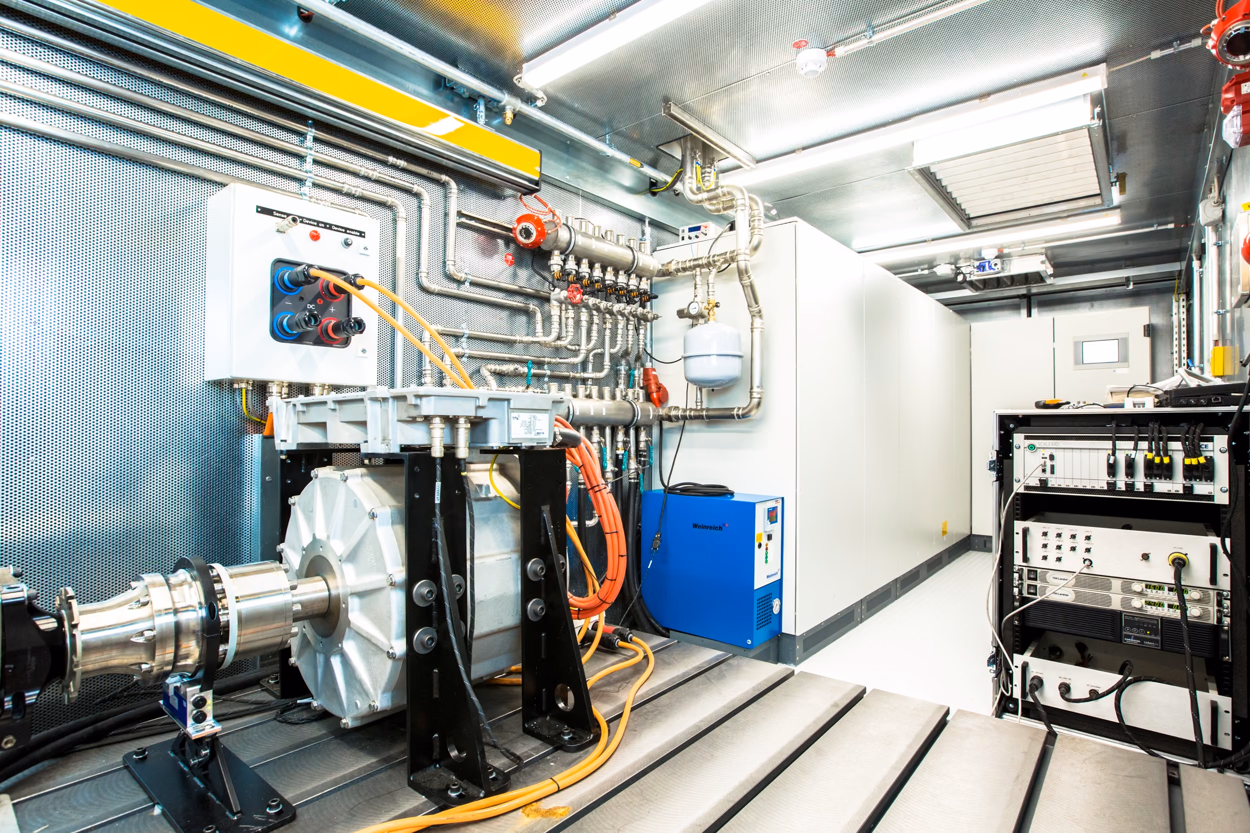
Powertrain-in-the-Loop testing works with the actual hardware. Real motors, inverters, and batteries operated under controlled, dynamic load conditions that reproduce realistic vehicle duty cycles. The control software runs against real hardware, not a representation of it — and what the integrated system actually does under those conditions is measured directly. This is not just software validation. It is hardware characterisation and integration validation in one environment.
Renco operates a Powertrain-in-the-Loop test bench in Cologne. It is owned and operated in-house, with a dSPACE Scalexio HIL simulator integrated directly into the bench.
What the PIL bench can test
The bench supports individual component testing and full system combinations. Motors, inverters, and batteries can be tested in isolation or together as an integrated drivetrain. An integrated e-axle unit with separate load and brake motors allows single-wheel control for differential and torque vectoring analysis.
The battery test section validates individual modules through to complete traction batteries, including charge and discharge cycle characterisation.
Technical specifications:
- Max continuous power: 250 kW
- Voltage range: 20–1000 Vdc (battery model implementable)
- Max braking torque per wheel: 3,500 Nm
- Max wheel speed: 3,375 rpm
- Cooling circuit: max coolant temperature 140°C, max flow 30 l/min, heating 2×4 kW, cooling 2×15 kW
What PIL testing tells you that HIL alone cannot
HIL tells you how the software responds to modelled hardware behaviour. PIL tells you how the software responds to real hardware behaviour — including the edge cases, thermal limits, and transient dynamics that models tend to smooth over.
Specific questions PIL can answer:
- Does the control software manage the powertrain correctly under continuous and peak load?
- How does the system behave at thermal limits — and does the thermal management strategy hold up under a real duty cycle?
- Are there interactions between control software and hardware that only appear under real operating conditions?
- Does brake energy recovery behave as expected across the full operating range?
- Does the battery management strategy perform correctly under realistic charge and discharge profiles?
How PIL fits into the development process
PIL testing is applied at the stage where simulation has done what it can and real hardware evidence is needed before committing to vehicle integration. It reduces the volume of field testing required and moves hardware-related risk earlier in the program — where it is cheaper and faster to address.
The dSPACE Scalexio integration means the same HIL toolchain used for software validation connects directly to the bench. Test configurations, driving simulations, and fault injection scenarios run in the same environment. Results are traceable to the same test framework used throughout the program.
HIL and PIL as a closed loop
Renco operates both HIL simulation environments and the PIL bench in-house. This means the relationship between the two is not just sequential — it is circular. Measurements from real hardware on the PIL bench feed back into the HIL plant models, improving their accuracy for future simulation runs. A motor characterised on the PIL bench produces a better model. A thermal behaviour measured under sustained load produces a more realistic simulation. The learning compounds in both directions, and the confidence in the results increases with each cycle.
Explore EV System Integration

Talk to engineers who’ve been here before
If you’re responsible for an EV program and want to reduce uncertainty before it becomes risk, let’s talk.
We’ll review your system reality and outline a clear, feasible next step.